It is known that a typical observer can discern between a dozen to three
dozen distinct grey levels or intensity variations. If color is added,
then a typical observer can discern thousands of color shades and
intensities.
Another important parameter is the data type of each element.
Data type refers to the number of bits required to represent each data element.
This information is important for determining the type of arithmetic
used for representing, processing, and displaying data elements.
To display data a transformation is made in order to generate a visual
representation. The actual data can be seen by moving the mouse over
the data and reading its values. This display transformation is very
complex and important to understand. Also, in many applications is
poorly implemented. The issues dealt with in this transformation are:
-
The image for our experiment is shown below. It is a 128x128 floating point
imageof a sinusoidal wave in the width direction.
The data type of the pixels is "float" and it varies between -2.0 and 2.0.
 ---
---
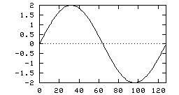
Left: Original image, data type "float", Right: plot of a single line
Clicking on the image will call the khoros display operator.
Observe that the true data value is displayed in floating point format
in the location window at the bottom of the image.
In this case, the data is mapped into the default grey scale, with its
maximum value (2.0) corresponding to the brightest shade (white) and
the minimum (-2.0) to the darkest shade (black).
-
Converting the original image to data type "bit" makes all data values greater
than zero to be converted to 1 and the rest to 0.
 ---
---

Converted image, data type "bit"
Observe that all "ones" are mapped to the brightest shade and all "zeros" to
the darkest.
-
If we convert the original image to data type "byte", the resultant image
has five different values: +2, +1, 0, -1 and -2 due to truncation.
 ---
---

Converted image, data type "byte"
Observe that the maximum value (2) is mapped to white, the minimum value (-2)
is mapped to black and the others to intermediate grey shades.
-
It is possible to perform data convertion to "byte" and visualize the
sinusoidal wave by scaling the original data values such that +2 is converted
to +127 and -2 to -127 using the scale and offset operation:
output = scale * input + offset.
If we convert the original image to data type "byte" with a scale factor
of 255/4, the display is as follows:
 ---
---

Converted image, data type "byte" with scaling factor 255/4
-
If we convert the original image to data type "unsigned byte",
the values will be converted following the table:
      x =   2   ==>  2
 1 <= x <   2   ==>  1
 0 <= x <   1   ==>  0
-1 <  x <   0   ==>  0
-2 <  x <= -1   ==>  255 (-1)
      x =  -2   ==>  254 (-2)
 ---
---
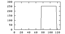
Converted image, data type "unsigned byte"
Observe that we cannot see the values 1 and 2 because 255 is mapped to the
brightest grey level, and we cannot discern from values 255 and 254 because
their shades are very similar.
-
If we convert the original image to data type "unsigned byte" with a
scale factor of 255/4 and an offset of 128, the output values range from
0 (original -2) to 255 (original +2).
 ---
---
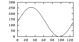
Converted image, data type "unsigned byte" with scaling and offset
-
All the above concepts are true for the other data types except "complex".
The "complex" data type is used in several Data Transforms such as Fourier,
Discrete Cosine, etc. The most common display technique to visualize a
"complex" value is to take the logarithm of its magnitude plus 1:
log(|x| + 1)
If we convert the original image to data type "complex", the resultant image
has the real part equivalent to the original pixels and the imaginary part
is set to zero.
 ---
---

Converted image, log(|x|+1), data type "complex"
The display transformation process performs an implicit conversion using
log(|x|+1) which generates an output range between 0 (log[0+1])
and log[2+1]. Zero is mapped to black
and log(3) is mapped to white. Note that image enhancement has occurred.
 ---
---

 ---
---

 ---
---

 ---
---

 ---
---

 ---
---

 ---
---
