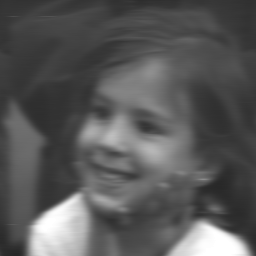
 -
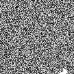
-
Left: blurred image, data type byte,
Right: difference between the float and byte type images
In the previous Inverse Filtering experiment we assumed an ideal situation that rarely exists. In this lesson we will use a more practical approach to image restoration.
In the Inverse Filtering lesson, the blurred image pixels are floating point. If that image is converted to unsigned byte data type, the consequence is similar to subtracting a constant distribution of noise with values from 0 to 1. Although these differences do not cause any problem with our visual perception of the image, it plays an important role in image restoration by the inverse filtering procedure.
 -
-
Left: blurred image, data type byte,
Right: difference between the float and byte type images
 -
-
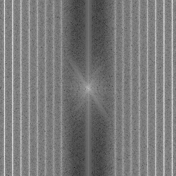
Left: spectrum of the blurred byte image,
Right: spectrum of the inverse filter
Notice that the DFT of the blurred byte image does not show any vertical stripes of low values. This is because the DFT of the noise was added to the spectrum. When using the inverse filtering technique, the problem encountered is that in the region of vertical high value stripes the noise is amplified and corrupts the restored image.
 -
-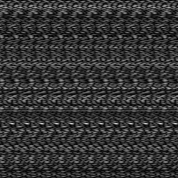
Left: division of blurred byte DFT by the kernel DFT,
Right: restored image
A practical solution to this problem is to define a threshold value in the magnitude of inverse kernel DFT where the division will take place. This can be depicted in the results shown below.

 -
-

Left: pseudo-inverse division of the blurred byte DFT by the kernel DFT,
Right: restored image