If image1 is AxB and image2 is CxD then:
a) if M = A + C - 1, periods in the width direction are adjacent
   if N = B + D - 1, periods in the height direction are adjacent
b) if M > A + C - 1, periods in the width direction will be separated
   if N > B + D - 1, periods in the height direction will be separated
c) if M < A + C - 1, periods in the width direction will overlap
   if N < B + D - 1, periods in the height direction will overlap
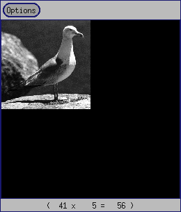
The dimensions of the original image "gull.viff" are 256x256, and the dimensions of the convolution kernel, Laplacian filter, are 3x3. This filter highlights details with a high frequency content, like edges. The Laplacian filter (other names are: window, mask, template, kernel) is depicted below, and is an ascii file with its origin or "sweet spot" at its center.
#
# Laplacian High-pass filter
#
 0.0 -1.0  0.0
-1.0  4.0 -1.0
 0.0 -1.0  0.0
In order to perform Linear convolution between the original image and filter kernel, we must first determine new dimensions to avoid the wraparound effect. One choice for a set of new dimensions is:
  M (new width) = 256 + 3 -1 = 258
  N (new height) = 256 + 3 -1 = 258
The difficulty with the new dimensions is that we cannot take advantage of the FFT to perform linear convolution. This is true because both the new width and height are not an integer power of two. We can zeropad both image and kernel to the next higher power of two, that is, 512x512, and then use the FFT to perform linear convolution.
In our experiment, we are going to follow this approach but first we are going to reduce or "shrink" the original image to 1/2 its size, i.e., 128x128. The reasoning behind this is to speed up the computations necessary. The reduced original image, and zero padded to 256x256 is shown below.
The results of the filtering operation in the frequency domain and in the spatial domain are depicted below. In addition, the difference of both results is also shown.
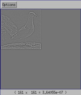
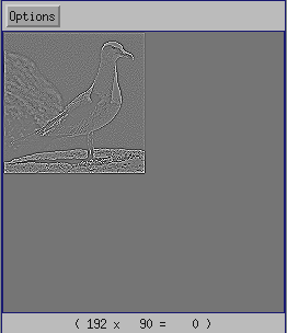
Frequency filtering ------------ Spatial filtering
The difference of the results yields
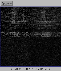
Difference
Observe that the difference image shows the existance of very small pixel values. These small pixel values are due to roundoff and truncation errors that appear when there is a limited number of bits to represent values.